Cisco Packet Tracer
Cisco Packet Tracer
Connect with me: Youtube | LinkedIn | WhatsApp Channel | Web | Facebook | Twitter
- Download PDF
-
To access the updated handouts, please click on the following link: https://yasirbhutta.github.io/tools/docs/cisco-packet-tracer.html
- How to configure DHCP server
- How to configure DNS server
- Configure DHCP on the Router
- Connecting Two LANs with a Router: A Step-by-Step Guide
Lab Task 1: Basic PC-to-PC Communication
Objective: Create a simple network where two PCs communicate with each other.
Steps:
- Drag two PCs onto the workspace.
- Drag a Switch and place it between the two PCs.
- Use Copper Cross-over cables to connect each PC to the switch.
- Click on PC1, go to the Desktop tab, and assign the following IP address:
IP: 192.168.1.1

Subnet Mask: 255.255.255.0
Do the same for PC2 with:
IP: 192.168.1.2

Subnet Mask: 255.255.255.0
- Test connectivity by opening a command prompt on PC1 and using the ping command to ping PC2.
Learning Outcome: Understand basic IP addressing and connectivity testing using the ping command.
Lab Task 2: Connecting Multiple PCs using a Switch
Objective: Build a small network with multiple PCs communicating via a switch.
Steps:
- Drag four PCs and one Switch (2960 Switch) onto the workspace.
- Use Copper Straight-Through cables to connect each PC to the switch.
- Assign the following IP addresses and subnet masks:
PC1: 192.168.1.1 / 255.255.255.0

PC2: 192.168.1.2 / 255.255.255.0

PC3: 192.168.1.3 / 255.255.255.0

PC4: 192.168.1.4 / 255.255.255.0
- Test connectivity by pinging each PC from another (e.g., from PC1, ping PC2, PC3, and PC4).
Learning Outcome: Understand how a switch enables communication between multiple devices on the same network.
1. How to configure DHCP server in Packet Tracer
Configuring a DHCP (Dynamic Host Configuration Protocol) server in Cisco Packet Tracer allows you to automate the assignment of IP addresses to devices on your network. Below is a step-by-step guide to setting up a DHCP server using Packet Tracer’s built-in server functionality. This guide assumes you have a basic understanding of networking concepts and Packet Tracer’s interface.
1. Set Up Your Network Topology
Before configuring the DHCP server, you need to set up a basic network topology. Here’s a simple example:
- Devices Needed:
- 1 Router
- 1 Switch
- 1 Server
- Multiple PCs (clients)
Steps:
- Open Packet Tracer:
- Launch Cisco Packet Tracer on your computer.
- Add Devices to the Workspace:
- From the device list at the bottom, drag and drop the following devices onto the workspace:
- Router: e.g., 2911 Router
- Switch: e.g., 2960 Switch
- Server: e.g., Generic Server
- PCs: Add as many as needed (e.g., 2 PCs)
- From the device list at the bottom, drag and drop the following devices onto the workspace:
- Connect the Devices:
- Use Copper Straight-Through cables to connect devices:
- Router to Switch: Connect the router’s GigabitEthernet0/0 interface to the switch’s FastEthernet0/1 port.
- Switch to Server: Connect the switch’s FastEthernet0/2 port to the server’s FastEthernet0 port.
- Switch to PCs: Connect each PC’s FastEthernet0 port to the switch’s FastEthernet0/3, FastEthernet0/4, etc.

- Use Copper Straight-Through cables to connect devices:
2. Configure the Router
The router will act as the default gateway for your network.
Steps:
- Access the Router’s CLI:
- Click on the router.
- Go to the CLI tab.
- Enter Configuration Mode:
Router> enable Router# configure terminal - Configure the Interface Connected to the Switch:
Router(config)# interface GigabitEthernet0/0 Router(config-if)# ip address 192.168.1.1 255.255.255.0 Router(config-if)# no shutdown Router(config-if)# exit - Enable DHCP on the Router (Optional):
- If you prefer to use the router as a DHCP server, you can skip to Configuring DHCP on the Router Otherwise, proceed to configure the dedicated server.
- Exit Configuration Mode:
Router(config)# exit
Router# write memory
3. Configure the Server as a DHCP Server
Using Packet Tracer’s built-in server functionality is straightforward.
Steps:
- Access the Server:
- Click on the Server device.
- Go to the Config tab or Services tab (depending on Packet Tracer version).
- Configure the Server’s IP Address:
- Ensure the server has a static IP address within the network range.
- Example Configuration:
- IP Address: 192.168.1.10
- Subnet Mask: 255.255.255.0
- Default Gateway: 192.168.1.1

- Set Up DHCP Service:
- Navigate to the Services tab.
- Click on DHCP from the left-hand menu.
- Click Add to create a new DHCP pool.
- Configure DHCP Pool Parameters:
- Default Gateway: 192.168.1.1
- DNS Server: You can use a public DNS server like 8.8.8.8 or specify your own.
- Start IP Address: 192.168.1.100
- Subnet Mask: 255.255.255.0
- Max Number of Users: Set according to the number of devices (e.g., 50)

- Save the Configuration:
- Ensure all settings are correctly entered.
- The DHCP server is now ready to assign IP addresses to clients.
4. Configure Client PCs to Use DHCP
Ensure that client devices are set to obtain their IP addresses automatically.
Steps:
- Access a PC:
- Click on a PC device.
- Go to the Desktop tab.
- Click on IP Configuration.
- Set IP Configuration to DHCP:
- Select DHCP.
- The PC should automatically receive an IP address from the DHCP server.

- Verify IP Address:
- After a few seconds, the PC should display an IP address within the DHCP pool range (e.g., 192.168.1.100).
- Repeat this step for all client PCs.
5. Verify DHCP Functionality
Ensure that DHCP is correctly assigning IP addresses to all clients.
Steps:
- Check IP Addresses on PCs:
- Each PC should have a unique IP address within the specified DHCP pool.
- The Default Gateway should be set to the router’s IP (192.168.1.1).
- The DNS Server should be as configured (e.g., 8.8.8.8).
- Ping Test:
- From a PC, open the Command Prompt (Desktop > Command Prompt).
- Ping the default gateway to ensure connectivity.
ping 192.168.1.1 - You should receive replies indicating successful communication.
- Check DHCP Server Lease Table:
- On the Server, go to the Services tab.
- Click on DHCP.
- Review the list of leased IP addresses to ensure all clients are receiving addresses.

6. Optional: Configure DHCP on the Router
If you prefer to use the router as your DHCP server instead of a dedicated server, follow these steps:
Steps:
- Access the Router’s CLI:
- Click on the Router device.
- Go to the CLI tab.
- Enter Configuration Mode:
Router> enable Router# configure terminal - Create a DHCP Pool:
Router(config)# ip dhcp pool LAN Router(dhcp-config)# network 192.168.1.0 255.255.255.0 Router(dhcp-config)# default-router 192.168.1.1 Router(dhcp-config)# dns-server 8.8.8.8 Router(dhcp-config)# exit - Exclude Addresses (Optional):
- To prevent the router from assigning certain IP addresses (e.g., for the router itself or servers), use the
ip dhcp excluded-addresscommand.Router(config)# ip dhcp excluded-address 192.168.1.1 192.168.1.10 Router(config)# exit Router# write memory
- To prevent the router from assigning certain IP addresses (e.g., for the router itself or servers), use the
- Configure Clients to Use DHCP:
- As previously described, set each PC to obtain an IP address automatically.
- Verify DHCP Assignments:
- Check the IP addresses on the PCs and perform connectivity tests as described earlier.
Troubleshooting Tips
- No IP Address Assigned:
- Ensure that the DHCP server is connected to the correct network.
- Verify that the DHCP service is enabled and properly configured on the server or router.
- Check that clients are set to obtain IP addresses automatically.
- IP Address Conflicts:
- Ensure that the DHCP pool does not overlap with any statically assigned IP addresses.
- Use the
ip dhcp excluded-addresscommand on routers to exclude specific IP ranges.
- Connectivity Issues:
- Verify all device interfaces are up (
no shutdownon router interfaces). - Check cable connections and ensure devices are properly connected to the switch.
- Verify all device interfaces are up (
Conclusion
Configuring a DHCP server in Packet Tracer simplifies network management by automating IP address assignments. Whether you choose to use a dedicated server or configure the router to handle DHCP duties, the process involves setting up the DHCP pool parameters and ensuring clients are set to receive IP addresses automatically. By following the steps outlined above, you can efficiently set up and verify a DHCP server in your simulated network environment.
2. How to configure DNS server in Packet Tracer
To configure a DNS server in Cisco Packet Tracer, follow these steps:
Step 1: Add Devices
- Add a DNS Server: Drag a server from the network devices list and place it on the workspace.
- Add a PC: Drag a PC to the workspace.
- Add a Router and Switch: Add a router and a switch to connect the DNS server and the PC.
Step 2: Connect the Devices
- Connect the devices using the appropriate cables (copper straight-through or crossover, depending on the type of connection).
- Make sure the server, PC, and router are all connected through the switch.
Step 3: Assign IP Addresses
-
Assign IP addresses to each device manually or use DHCP for automatic IP assignment.
- DNS Server:
- Click on the DNS Server.
- Go to the Desktop tab, click on IP Configuration, and assign a static IP address (e.g., 192.168.1.2).
- PC:
- Click on the PC.
- Go to the Desktop tab, click on IP Configuration, and assign an IP address (e.g., 192.168.1.3) with the appropriate subnet mask and default gateway (e.g., 192.168.1.1 for the router).
- DNS Server:
Step 4: Configure DNS Server
- Click on the DNS Server.
- Go to the Services tab and select DNS.
- Turn on the DNS service by clicking the ON button.
- Add DNS records:
- Record #1:
- Enter the domain name (e.g.,
www.example.com). - Enter the corresponding IP address (e.g., 192.168.1.3).
- Click on Add to add the
A Record. - Record #2: - Enter the domain name (e.g.,
gudgk.edu.pk). - Enter the corresponding IP address (e.g., 192.168.1.8).
- Click on Add to add the
A Record.
Step 5: Configure PC to Use DNS
- Go to the PC and open the Desktop tab.
- Open the IP Configuration.
- In the DNS Server field, enter the IP address of the DNS server (e.g., 192.168.1.2).
Step 6: Test the DNS Configuration
- Go to the PC and open the Command Prompt from the Desktop tab.
- Type the following command to test if the DNS resolution works:
ping www.example.com - If the DNS server is correctly configured, the PC will be able to resolve the domain name to the IP address and respond to the ping.
Task #3:
To create the network diagram in Cisco Packet Tracer based on the whiteboard image, follow these steps:
Devices and IPs:
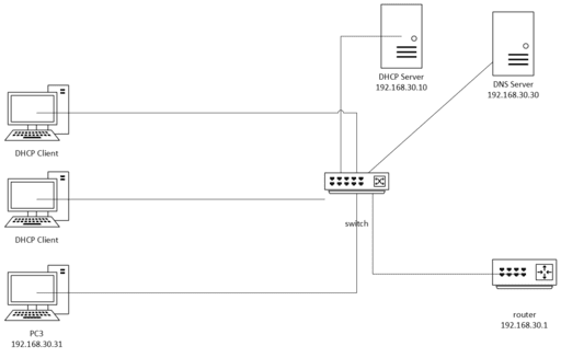
- Router:
IP Address: 192.168.30.1
- DHCP Server:
IP Address: 192.168.30.10
Assign IP addresses from the range 192.168.30.160 onwards
- DNS Server:
IP Address: 192.168.30.30
- PC1 and PC2 (DHCP Clients):
Connected to a switch, both configured as DHCP clients to obtain IPs dynamically.
- PC3:
Static IP: 192.168.30.31
- Switch:
All PCs, DHCP, and DNS servers are connected through this switch.
Steps in Cisco Packet Tracer:
- Add devices:
Drag a Router, Switch, 3 PCs, DHCP Server, and DNS Server onto the workspace.
- Configure the Router:
Go to the Router -> Config tab, assign the IP address 192.168.30.1 to the appropriate interface (e.g., GigabitEthernet0/0).
- Configure the DHCP Server:
Set the IP address of the DHCP Server to 192.168.30.10.
Go to the Services tab and configure DHCP. Set the start IP range to 192.168.30.160.
- Configure the DNS Server:
Assign the IP address 192.168.30.30 to the DNS server.
In the Services tab, configure DNS with any domain names you want to resolve.
- Add five DNS entries by filling out the fields as follows:
| Domain Name | IP Address |
|---|---|
| example.com | 192.168.30.50 |
| site.local | 192.168.30.60 |
| network.internal | 192.168.30.70 |
| appserver.company | 192.168.30.80 |
| database.service | 192.168.30.90 |
- Configure the PCs:
PC1 and PC2: Go to each PC, and in the IP Configuration tab, set the IP configuration to DHCP.
PC3: Manually configure its IP address to 192.168.30.31 in the Static IP section.
- Connect all devices:
Use cables to connect the devices to the switch (PCs, DHCP, DNS Server).
Connect the switch to the router.
- Test connectivity:
- Once the network is built, test the network by pinging the router from each PC, and check DHCP functionality on PC1 and PC2.
- Test DNS Resolution:
- From PC1, PC2, or PC3, use the Command Prompt (CLI) to test the DNS resolution by pinging the domain names (e.g., ping example.com). If DNS is properly configured, it will resolve the domain name to the associated IP address.
To check connectivity between PCs in different subnets as represented in your diagram, you can perform the following tasks:
Task #4: Connect PCs with different subnet
Step 1: Assign IP Addresses
Make sure that all the PCs are configured with the IP addresses shown in the diagram:
PC1: 192.168.2.10
PC2: 192.168.2.11
PC3: 192.168.1.10
PC4: 192.168.1.11
Step 2: Ping Test within the Same Subnet
- Ping between PC1 and PC2 (same subnet: 192.168.2.x):
From PC1, open the terminal and run:
ping 192.168.2.11
From PC2, run:
ping 192.168.2.10
- Ping between PC3 and PC4 (same subnet: 192.168.1.x):
From PC3, open the terminal and run:
ping 192.168.1.11
From PC4, run:
ping 192.168.1.10
Step 3: Ping Test Across Different Subnets
- Ping between PC1 (192.168.2.10) and PC3 (192.168.1.10):
From PC1, run:
ping 192.168.1.10
From PC3, run:
ping 192.168.2.10
- Ping between PC2 (192.168.2.11) and PC4 (192.168.1.11):
From PC2, run:
ping 192.168.1.11
From PC4, run:
ping 192.168.2.11
Tips: A router or Layer 3 switch is configured for routing between subnets.
By completing these tasks, you can check the connectivity between PCs in the same and different subnets.
3. Connecting Two LANs with a Router: A Step-by-Step Guide
Connecting two Local Area Networks (LANs) using a router allows devices on different networks to communicate with each other.
Network Diagram
[LAN 1] ------ [Router] ------ [LAN 2]
Equipment Needed
- Router: A device that forwards data packets between networks.
- Two LANs: Each can consist of switches and devices (like PCs).
- Ethernet Cables: To connect the router to the switches or devices.
Step-by-Step Guide
Connecting two Local Area Networks (LANs) using a router in Cisco Packet Tracer involves several steps, including configuring the router and the devices within each LAN. Here’s a detailed guide to help you set up this connection:
Step 1: Open Cisco Packet Tracer
- Launch Cisco Packet Tracer on your computer.
Step 2: Add Devices
- Add a Router: Drag and drop a router (e.g., a 2911 router) onto the workspace.
- Add Switches: Drag and drop two switches (e.g., 2960 switches) onto the workspace.
- Add PCs: Add at least one PC to each switch (e.g., PC1 on Switch1 and PC2 on Switch2).
Step 3: Connect Devices
- Connect the PCs to the Switches:
- Use the Connections tool (cable icon) and select Copper Straight-Through cable.
- Connect PC1 to Switch1 (e.g., FastEthernet 0/1).
- Connect PC2 to Switch2 (e.g., FastEthernet 0/1).
- Connect the Switches to the Router:
- Use the Copper Straight-Through cable.
- Connect Switch1 to the router’s GigabitEthernet 0/0 port.
- Connect Switch2 to the router’s GigabitEthernet 0/1 port.
Step 4: Configure the Router
- Access the Router CLI:
- Click on the router and go to the CLI tab.
- Press
Enterto access the command line interface.
- Enter Global Configuration Mode:
Router> enable
Router# configure terminal
optional to show interfaces
Router# show interfaces
- Configure Interfaces:
- For FastEthernet 0/0 (connecting to LAN1):
Router(config)# interface GigabitEthernet0/0 # Gi0/0 or G0/0 would refer to GigabitEthernet0/0. Router(config-if)# ip address 192.168.1.1 255.255.255.0 # Assigning IP address Router(config-if)# no shutdown # Activating the interface - For GigabitEthernet 0/1 (connecting to LAN2):
- For FastEthernet 0/0 (connecting to LAN1):
Router(config)# interface GigabitEthernet0/1 # Gi0/1 or G0/1 would refer to GigabitEthernet0/1.
Router(config-if)# ip address 192.168.2.1 255.255.255.0  # Assigning IP address
Router(config-if)# no shutdown  # Activating the interface
Step 5: Configure the PCs
- Configure PC1 (in LAN1):
- Click on PC1 and go to the Desktop tab.
- Click on IP Configuration and set:
- IP Address:
192.168.1.2 - Subnet Mask:
255.255.255.0 - Default Gateway:
192.168.1.1
- IP Address:
- Configure PC2 (in LAN2):
- Click on PC2 and go to the Desktop tab.
- Click on IP Configuration and set:
- IP Address:
192.168.2.2 - Subnet Mask:
255.255.255.0 - Default Gateway:
192.168.2.1
- IP Address:
Step 7: Test Connectivity
- Ping Between PCs:
- Open the command prompt on PC1 and type:
ping 192.168.2.2 # This pings PC2 in LAN2 - You should receive replies if everything is configured correctly.
- Open the command prompt on PC1 and type:
Step 8: Save Configuration
- Save the Router Configuration:
Router# write memory - Save the Switch Configuration (if applicable):
Switch# write memory
Additional Notes
- Routing: If you need to enable routing between the two LANs, ensure the router has routing enabled, which is typically the case by default.
Conclusion
By following these steps, you can successfully connect two LANs using a router in Cisco Packet Tracer. This setup allows devices from one LAN to communicate with devices on another LAN, demonstrating the fundamental concept of routing in computer networks. If you have any further questions or need additional details, feel free to ask!
Router Configuration with Two Subnets
Objective: Create two networks with different subnets and connect them using a router.
Steps:
- Drag two Switches and a Router onto the workspace.
- Connect two PCs to Switch 1 and two PCs to Switch 2 using Copper Straight-Through cables.
- Connect Switch 1 to the Router’s GigabitEthernet 0/0 interface and Switch 2 to the Router’s GigabitEthernet 0/1 interface.
- Assign the following IP addresses and subnet masks:
PCs connected to Switch 1:
PC1: 192.168.1.2 / 255.255.255.0 PC2: 192.168.1.3 / 255.255.255.0
PCs connected to Switch 2:
PC3: 192.168.2.2 / 255.255.255.0 PC4: 192.168.2.3 / 255.255.255.0
- Configure the router’s interfaces:
Interface Gig0/0: 192.168.1.1 / 255.255.255.0 Interface Gig0/1: 192.168.2.1 / 255.255.255.0
- Test connectivity by pinging across subnets (e.g., PC1 to PC3).
Learning Outcome: Learn basic router configuration to enable communication between different subnets.
How to Configure VLANS
Using Cisco Packet Tracer, we can set up a VLAN configuration step-by-step. Let’s create a simple network with two VLANs for two different departments: Sales and Engineering. This example will guide you through configuring VLANs on a Cisco switch.
Scenario
- We’ll create two VLANs: VLAN 10 for Sales and VLAN 20 for Engineering.
- We’ll connect two PCs for each VLAN to the switch and assign them to the appropriate VLAN.
- We’ll also assign IP addresses to each PC so they can communicate within their VLAN but not across VLANs (without routing).
Step-by-Step Guide
1. Open Cisco Packet Tracer and Set Up Devices
- Open Cisco Packet Tracer.
- Drag and drop a 2960 switch onto the workspace.
- Add four PCs (two for Sales and two for Engineering).
- Connect each PC to the switch using Copper Straight-Through cables.
2. Assign PC Ports on the Switch
- Connect the PCs to specific switch ports:
- PC0 (Sales) to Switch Port FastEthernet0/1
- PC1 (Sales) to Switch Port FastEthernet0/2
- PC2 (Engineering) to Switch Port FastEthernet0/3
- PC3 (Engineering) to Switch Port FastEthernet0/4
3. Configure VLANs on the Switch
- Click on the switch, then go to the CLI tab to access the command-line interface.
-
Enter configuration mode to create the VLANs.
enable configure terminal -
Create VLAN 10 for Sales:
vlan 10 name Sales -
Create VLAN 20 for Engineering:
vlan 20 name Engineering -
Exit VLAN configuration mode:
exit
4. Assign Switch Ports to VLANs
-
Now, assign the ports connected to Sales PCs to VLAN 10 and Engineering PCs to VLAN 20.
-
Assign FastEthernet0/1 and FastEthernet0/2 to VLAN 10:
# FastEthernet0/1 is often abbreviated as Fa0/1 interface FastEthernet0/1 switchport mode access switchport access vlan 10 exit interface FastEthernet0/2 switchport mode access switchport access vlan 10 exit -
Assign FastEthernet0/3 and FastEthernet0/4 to VLAN 20:
interface FastEthernet0/3
switchport mode access
switchport access vlan 20
exit

interface FastEthernet0/4
switchport mode access
switchport access vlan 20
exit
Switch# write memory
5. Configure IP Addresses for Each PC
-
Now, assign IP addresses to each PC according to the VLAN they belong to.
- For Sales PCs (VLAN 10):
- PC0: IP Address 192.168.10.1, Subnet Mask 255.255.255.0
- PC1: IP Address 192.168.10.2, Subnet Mask 255.255.255.0
- For Engineering PCs (VLAN 20):
- PC2: IP Address 192.168.10.20, Subnet Mask 255.255.255.0
- PC3: IP Address 192.168.10.21, Subnet Mask 255.255.255.0
- To set IP addresses, click on each PC, go to the Desktop tab, and select IP Configuration. Enter the IP address and subnet mask accordingly.
To check the VLAN configuration on a Cisco switch, you can use the following commands in privileged EXEC mode:
Show VLANs
- This command displays all VLANs configured on the switch, including VLAN IDs, names, and ports assigned to each VLAN.
show vlan brief
Output Example:
   VLAN Name                             Status    Ports
   ---- -------------------------------- --------- ----------------
   1    default                          active    Fa0/1, Fa0/2
   10   Sales                            active    Fa0/3, Fa0/4
   20   Engineering                      active    Fa0/5, Fa0/6
6. Test Connectivity
- Now, test connectivity within each VLAN.
-
Open the Command Prompt on each PC and use the
pingcommand to test connectivity:- From PC0, ping PC1 (both in VLAN 10) using:
ping 192.168.10.2It should succeed.
- From PC2, ping PC3 (both in VLAN 20) using:
ping 192.168.10.20This should also succeed.
- From PC0, ping PC1 (both in VLAN 10) using:
- Try pinging across VLANs, such as from PC0 to PC2. The ping should fail because VLANs are isolated, and devices in different VLANs can’t communicate without a router or Layer 3 device.
Summary
This setup demonstrates how to create and assign VLANs on a Cisco switch using Cisco Packet Tracer. Each VLAN can only communicate within its own network segment, providing network segmentation and increased security.
Configure a Web Server
To configure a web server using Cisco Packet Tracer, follow these steps:
Step 1: Open Cisco Packet Tracer
Launch Cisco Packet Tracer and open a new workspace.
Step 2: Add Devices
- Add a PC: From the device list, select a PC and place it on the workspace.
- Add a Server: Select a server device and place it on the workspace.
- Add a Switch: Place a switch to connect the devices.
Step 3: Connect the Devices
Use a copper straight-through cable to connect:
- PC to the Switch.
- Server to the Switch.
Step 4: Configure the Server (Web Server)
-
Click on the Server to open its configuration panel.
-
Go to the Desktop tab and select IP Configuration.
Assign an IP address to the server, e.g., 192.168.1.2.
Set the subnet mask, e.g., 255.255.255.0.
Leave the default gateway blank for now if it’s a simple setup.
-
Go to the Services tab.
-
Click on HTTP and turn on the HTTP service (it’s usually on by default).
Optionally, turn on the HTTPS service for secure connections.
Step 5: Configure the PC
-
Click on the PC to open its configuration panel.
-
Go to the Desktop tab and select IP Configuration.
Assign an IP address, e.g., 192.168.1.3.
Use the same subnet mask as the server, e.g., 255.255.255.0.
Set the default gateway to 192.168.1.1 (if required for external routing).
Step 6: Test Connectivity
- Ping the Server from the PC:
Go to the PC’s Desktop, open the Command Prompt, and type:
ping 192.168.1.2
If the ping is successful, the connection is working.
Step 7: Access the Web Server
-
On the PC, open the Web Browser from the Desktop tab.
-
In the URL bar, enter the server’s IP address, e.g., http://192.168.1.2.
-
The web browser should display the default web page hosted by the Packet Tracer server.
Step 8: (Optional) Customize Web Content
-
In the Services tab of the server, under HTTP, you can modify the content of the web page (e.g., index.html) by editing the file.
-
This allows you to serve custom content to clients accessing the web server.
Step 9: Save Your Work
Once everything is working, save your project for future reference.
Upload a custom index.html page on a web server
This basic configuration sets up a web server in Cisco Packet Tracer for a small network.
To upload a custom index.html page on a web server in Cisco Packet Tracer, follow these steps:
Step 1: Open the Server Configuration
- Click on the Server that you want to configure in the workspace.
- Go to the Services tab.
Step 2: Navigate to the HTTP Service
- In the Services tab, select HTTP from the list of services on the left side.
- In the HTTP section, you’ll see the list of default files such as index.html.
Step 3: Upload or Edit the index.html Page
- Under Files, locate index.html.
You can either edit this file directly or upload your own HTML file.
- To edit the existing index.html:
Click on the file name (index.html) and a text editor will appear where you can modify the contents of the web page.
Replace the default HTML content with your custom HTML code.
- To upload a new index.html:
Click the Upload button (if available) and browse for the index.html file from your computer (this option is not always available depending on the version of Packet Tracer you’re using).
Step 4: Save the Changes
Once you’ve edited or uploaded the HTML file:
- Click Save to ensure your changes are applied.
- The updated index.html will now be hosted on the web server.
Step 5: Access the Web Page from a PC
- On the PC, open the Web Browser from the Desktop tab.
- Enter the IP address of the server in the URL field, e.g., http://192.168.1.2.
- The browser should now display your custom index.html page.
This process allows you to customize the web content served by the server in Cisco Packet Tracer.
Configure a DNS server to redirect a domain name
To configure a DNS server in Cisco Packet Tracer to redirect a domain name (e.g., www.example.com) to a specific website hosted on a web server, follow these steps:
Step 1: Set up Devices
Ensure you have the following devices already placed and connected in Cisco Packet Tracer:
- PC (to access the website)
- Web Server (hosting the website)
- DNS Server
- Switch (to connect all devices)
- Router (optional, if simulating a more complex network)
Step 2: Configure the Web Server
- Click on the Web Server and go to the Desktop tab.
- Click on IP Configuration and assign an IP address (e.g., 192.168.1.2), subnet mask (e.g., 255.255.255.0), and default gateway if required.
- Go to the Services tab and make sure the HTTP service is turned on (under HTTP).
Step 3: Configure the DNS Server
- Click on the DNS Server and go to the Desktop tab.
- Open IP Configuration and assign an IP address to the DNS server (e.g., 192.168.1.1), subnet mask (e.g., 255.255.255.0), and default gateway if necessary.
- Go to the Services tab and click on DNS in the list of services on the left.
- Turn on the DNS service if it is not already enabled.
- Add a new A (Address) Record:
Under Name, enter the domain name you want to use (e.g., www.example.com).
Under Address, enter the IP address of the web server (e.g., 192.168.1.2).
Click Add to add this DNS entry.
Step 4: Configure the PC
- Click on the PC and go to the Desktop tab.
- Open IP Configuration and assign an IP address to the PC (e.g., 192.168.1.3), subnet mask (e.g., 255.255.255.0), and default gateway (e.g., 192.168.1.254).
- In the DNS Server field, enter the IP address of the DNS server (e.g., 192.168.1.1).
Step 5: Test the DNS Configuration
- On the PC, go to the Desktop tab and open the Command Prompt.
- Test the DNS resolution by typing:
ping www.example.com
This should resolve to the IP address of the web server (192.168.1.2).
- To access the website, open the Web Browser on the PC and type the domain name (e.g., http://www.example.com) in the URL field.
You should be redirected to the website hosted on the web server.
Step 6: Save the Configuration
After verifying that everything works, save your Packet Tracer project.
This setup allows you to configure a DNS server that resolves a domain name to the IP address of a web server, effectively redirecting the domain to the website.
Task: Design and Configure a Multi-Subnet Network Topology with DHCP, DNS, and Web Server Integration in Cisco Packet Tracer
- Set Up Devices:
- Add one Router to represent
192.168.1.1. - Add one Switch connected to the router for the
192.168.1.xsubnet. - Add the following devices to the switch:
- DHCP Server with IP
192.168.1.7. - Three DHCP Clients (configure them to obtain IP addresses dynamically from the DHCP server).
- DHCP Server with IP
- Add one Router to represent
- Add the Second Subnet:
- Connect the router to a second Switch for the
192.168.10.xsubnet. - Add the following devices to this switch:
- Web Server with IP
192.168.10.10. - DNS Server with IP
192.168.10.20.
- Web Server with IP
- Connect the router to a second Switch for the
- Configure the Router:
- Set up two interfaces on the router:
- Interface for Subnet 1: Assign IP
192.168.1.1. - Interface for Subnet 2: Assign IP
192.168.10.1.
- Interface for Subnet 1: Assign IP
- Set up two interfaces on the router:
- DHCP Server Configuration:
- On the DHCP Server, configure a DHCP pool for
192.168.1.xwith:- Gateway:
192.168.1.1. - IP Range: Assign IPs dynamically (e.g.,
192.168.1.100to192.168.1.200).
- Gateway:
- On the DHCP Server, configure a DHCP pool for
- DNS Server Configuration:
- On the DNS server, set up domain name resolution (e.g., resolve the hostname
www.example.comto192.168.10.10).
- On the DNS server, set up domain name resolution (e.g., resolve the hostname
- Web Server Configuration:
- On the Web Server, host a basic website for testing (e.g., display “Welcome to the Network”).
- Connectivity Testing:
- Test the following:
- DHCP clients should receive IP addresses automatically from the DHCP Server.
- DHCP clients should be able to access the Web Server using both its IP (
192.168.10.10) and domain name (via the DNS Server). - Verify that devices in both subnets can ping each other through the router.
- Test the following:
- Optional Task:
- Implement basic security settings like:
- Restrict web server access to specific IPs.
- Enable port filtering on the router.
- Implement basic security settings like:
Task: “Interconnecting Two Networks with Router-to-Router Connectivity and Routing Using Cisco Packet Tracer”
- Open Cisco Packet Tracer:
- Launch the Packet Tracer software.
- Place Devices:
- Add two routers to the workspace. These will correspond to the two routers in your diagram.
- Add two switches and connect one switch to each router.
- Add three PCs to the left switch and one PC to the right switch.
- Interconnect the Devices:
- Use straight-through cables to connect:
- Each PC to the corresponding switch.
- Each switch to the respective router’s Ethernet interface.
- Use a serial Copper Cross-Over cable to connect the two routers via their serial interfaces.
- Use straight-through cables to connect:
- Configure IP Addresses:
- Assign the following IP ranges:
- Left network:
192.168.1.x - Right network:
192.168.10.x
- Left network:
- Configure router interfaces with the following IP addresses:
- Router1:
- Interface connected to the switch:
192.168.1.1 - Serial interface connecting to Router2: e.g.,
192.168.2.1
- Interface connected to the switch:
- Router2:
- Serial interface connecting to Router1: e.g.,
192.168.2.2 - Interface connected to the switch:
192.168.10.1
- Serial interface connecting to Router1: e.g.,
- Router1:
- Assign static IPs to PCs within their respective subnets.
- Assign the following IP ranges:
- Configure Routing:
- Enable routing on both routers by configuring static routes:
- On Router1:
ip route 192.168.10.0 255.255.255.0 192.168.2.2 - On Router2:
ip route 192.168.1.0 255.255.255.0 192.168.2.1
- On Router1:
- Enable routing on both routers by configuring static routes:
- Test Connectivity:
- Use the
pingcommand from one PC to another PC in the other network to verify connectivity. - Troubleshoot if the ping fails by checking IP configurations, routes, and cable connections.
- Use the
##
Here’s an updated task incorporating a Class B network for the connections between routers and Class C private networks for the LANs.
Task: Configuring Multi-LAN Networks with Class B Inter-Router Connections and Class C LAN Subnets in Cisco Packet Tracer
Objective: Simulate a network with Class B subnets for inter-router connections and Class C private subnets for LANs. Configure IP addressing, routing, and basic connectivity.
Guidelines:
Step 1: Network Setup
- Devices Required:
- 3 Routers: Connect the LANs and interconnect the networks.
- 3 Switches: Connect hosts and servers within each LAN.
- 1 DHCP Server: For dynamic IP allocation in LAN1.
- 1 DNS Server: For domain name resolution in LAN1.
- 1 Web Server: For hosting a webpage in LAN2.
- 6 PCs: Distribute across all LANs (e.g., 2 PCs per LAN).
- Network Topology:
- LAN1:
- Subnet:
192.168.1.0/24 - DHCP, DNS Server connected to a switch.
- 2 PCs connected to the switch.
- Subnet:
- LAN2:
- Subnet:
192.168.2.0/24 - Web Server connected to a switch.
- 2 PCs connected to the switch.
- Subnet:
- LAN3:
- Subnet:
192.168.3.0/24 - 2 PCs connected to a switch.
- Subnet:
- LAN1:
- Inter-Router Connections (Class B Subnets):
- Router-to-Router connections will use Class B subnets:
172.16.4.0/30for Router 1 ↔ Router 2 (subnet mask 255.255.255.252)172.16.5.0/30for Router 2 ↔ Router 3
- Router-to-Router connections will use Class B subnets:
Step 2: IP Addressing
- LAN IPs (Class C):
- LAN1:
- Router 1 Interface:
192.168.1.1/24 - DHCP Server Scope:
192.168.1.10-192.168.1.254
- Router 1 Interface:
- LAN2:
- Router 2 Interface:
192.168.2.1/24 - Static IP for Web Server:
192.168.2.10
- Router 2 Interface:
- LAN3:
- Router 3 Interface:
192.168.3.1/24 - Static IP for Web Server:
192.168.3.10
- Router 3 Interface:
- LAN1:
- Router Interconnections (Class B):
- Router 1 ↔ Router 2:
- Router 1 Interface:
172.16.4.1/30 - Router 2 Interface:
172.16.4.2/30
- Router 1 Interface:
- Router 2 ↔ Router 3:
- Router 2 Interface:
172.16.5.1/30 - Router 3 Interface:
172.16.5.2/30
- Router 2 Interface:
- Router 1 ↔ Router 2:
Step 3: Configure DHCP Server
- Configure the DHCP server to dynamically allocate IPs in LAN1 (
192.168.1.0/24). - Set the default gateway to
192.168.1.1(Router 1).
Step 4: Configure DNS Server
- Set the DNS server to resolve domain names (e.g.,
www.example.comto192.168.2.10). - Assign a static IP (e.g.,
192.168.1.10) to the DNS server. - Set the DNS server to resolve domain names (e.g.,
www.google.comto192.168.3.10). - Assign a static IP (e.g.,
192.168.1.10) to the DNS server.
Step 5: Configure Web Server
- Assign a static IP (
192.168.2.10) to the Web Server in LAN2 - Assign a static IP (
192.168.3.10) to the Web Server in LAN3. - Host a sample webpage and ensure it is accessible using its IP and domain name.
Step 5: Default Gateway
- LAN Devices:
- Configure PCs in LAN1, LAN2, and LAN3 with their respective gateways:
- LAN1: Gateway
192.168.1.1 - LAN2: Gateway
192.168.2.1 - LAN3: Gateway
192.168.3.1
- LAN1: Gateway
-
Step 6: Configure Routing
- Configure PCs in LAN1, LAN2, and LAN3 with their respective gateways:
- Enable routing between LANs and across routers:
- Use static routes on all routers or configure dynamic routing protocols (RIP or OSPF).
- Example (Static Route for Router 1):
ip route 192.168.2.0 255.255.255.0 172.16.4.2 ip route 192.168.3.0 255.255.255.0 172.16.4.2 - Example (Static Route for Router 2):
ip route 192.168.1.0 255.255.255.0 172.16.4.1 ip route 192.168.3.0 255.255.255.0 172.16.5.2 - Example (Static Route for Router 3):
ip route 192.168.2.0 255.255.255.0 172.16.5.1
ip route 192.168.3.0 255.255.255.0 172.16.5.1
Step 7: Test Connectivity
- Use the ping tool to test:
- Connectivity between PCs within the same LAN.
- Connectivity between PCs across different LANs.
- Connectivity to the Web Server from PCs in LAN1 and LAN3.
- Use a web browser to verify access to the hosted webpage.
RIP (Routing Information Protocol)
RIP (Routing Information Protocol) is one of the oldest and simplest distance-vector routing protocols used to determine the best path for data packets in a network. It works by sharing routing tables between routers at regular intervals.
Versions of RIP:
RIPv1: Classful (does not support subnet masks). Broadcasts updates.
RIPv2: Classless (supports subnet masks). Uses multicasts for routing updates. Supports authentication.
RIPng: Designed for IPv6 networks.
Task: Configuring Multi-LAN Networks with RIP Protocol in Cisco Packet Tracer
Objective: Simulate a network with Class B subnets for inter-router connections and Class C private subnets for LANs. Use RIP (Routing Information Protocol) to enable dynamic routing between routers and ensure connectivity across LANs.
Guidelines:
Step 1: Network Setup
- Devices Required:
- 3 Routers: Connect the LANs and manage routing.
- 3 Switches: Connect hosts and servers within each LAN.
- 1 DHCP Server: For dynamic IP allocation in LAN1.
- 1 DNS Server: For domain name resolution in LAN1.
- 1 Web Server: For hosting a webpage in LAN2.
- 6 PCs: Distribute across all LANs (2 PCs per LAN).
- Network Topology:
- LAN1:
- Subnet:
192.168.1.0/24 - DHCP and DNS Servers connected to a switch.
- 2 PCs connected to the switch.
- Subnet:
- LAN2:
- Subnet:
192.168.2.0/24 - Web Server connected to a switch.
- 2 PCs connected to the switch.
- Subnet:
- LAN3:
- Subnet:
192.168.3.0/24 - 2 PCs connected to a switch.
- Subnet:
- LAN1:
- Inter-Router Connections (Class B Subnets):
- Router-to-Router connections will use Class B subnets:
172.16.4.0/30for Router 1 ↔ Router 2172.16.5.0/30for Router 2 ↔ Router 3
- Router-to-Router connections will use Class B subnets:
Step 2: IP Addressing
- LAN IPs (Class C):
- LAN1:
- Router 1 Interface:
192.168.1.1/24 - DHCP Server Scope:
192.168.1.10-192.168.1.254
- Router 1 Interface:
- LAN2:
- Router 2 Interface:
192.168.2.1/24 - Static IP for Web Server:
192.168.2.10
- Router 2 Interface:
- LAN3:
- Router 3 Interface:
192.168.3.1/24
- Router 3 Interface:
- LAN1:
- Router Interconnections (Class B):
- Router 1 ↔ Router 2:
- Router 1 Interface:
172.16.4.1/30 - Router 2 Interface:
172.16.4.2/30
- Router 1 Interface:
- Router 2 ↔ Router 3:
- Router 2 Interface:
172.16.5.1/30 - Router 3 Interface:
172.16.5.2/30
- Router 2 Interface:
- Router 1 ↔ Router 2:
Step 3: Configure DHCP Server
- Assign the DHCP server an IP address within LAN1 (e.g.,
192.168.1.2). - Configure the DHCP scope to dynamically allocate IPs to devices in LAN1 (
192.168.1.10 - 192.168.1.254). - Set the default gateway to
192.168.1.1.
Step 4: Configure DNS Server
- Assign the DNS server a static IP in LAN1 (e.g.,
192.168.1.3). - Configure the DNS server to resolve:
www.example.com→192.168.2.10(Web Server in LAN2).www.test.com→192.168.3.10(Web Server in LAN3).
Step 5: Configure Web Servers
- Assign static IPs to web servers:
- LAN2 Web Server:
192.168.2.10. - LAN3 Web Server:
192.168.3.10.
- LAN2 Web Server:
- Host sample webpages and ensure they are accessible using their respective IPs.
Step 6: Configure RIP Protocol
- Enable RIP on each router:
- Enter global configuration mode:
Router> enable Router# configure terminal - Enable RIP and use version 2:
Router(config)# router rip Router(config-router)# version 2 - Add the networks associated with each router:
- Router 1:
Router(config-router)# network 192.168.1.0 Router(config-router)# network 172.16.4.0 - Router 2:
Router(config-router)# network 192.168.2.0 Router(config-router)# network 172.16.4.0 Router(config-router)# network 172.16.5.0 - Router 3:
Router(config-router)# network 192.168.3.0
Router(config-router)# network 172.16.5.0
- Router 1:
- Exit and save the configuration:
Router(config-router)# exit
Router# write memory
- Enter global configuration mode:
see Appendix B to learn the Importance of Configuring Network Addresses in RIP Protocol
Step 7: Test Connectivity
- Ping Tests:
- Test connectivity between PCs in the same LAN.
- Test connectivity between PCs across different LANs.
- Test connectivity from PCs to the Web Servers.
- Web Access:
- Use a browser to access webpages hosted on the Web Servers using:
- IP addresses (e.g.,
192.168.2.10). - Domain names (e.g.,
www.example.com).
- IP addresses (e.g.,
- Use a browser to access webpages hosted on the Web Servers using:
- RIP Verification:
- Check RIP routing tables on each router:
Router# show ip route
- Check RIP routing tables on each router:
Expected Outcome
- All devices within the network are reachable.
- Web Servers are accessible by both IP address and domain name.
- RIP dynamically routes packets across routers, ensuring connectivity between all LANs.
Appendices
Appendix A: Configuring DHCP on the Router
To configure a DHCP (Dynamic Host Configuration Protocol) server in Cisco Packet Tracer, follow these steps:
Step 1: Add Devices to the Network
- Open Cisco Packet Tracer.
- Add a server device (from the “End Devices” section) and a router or switch to the workspace.
- Add a PC or any other device that will obtain its IP address via DHCP.
Step 2: Configure the DHCP Server
- Click on the Server.
- In the Physical tab, ensure the correct module (if required) is installed.
- Switch to the Config tab.
- On the left menu, select DHCP.
- Turn on the DHCP service by toggling the button to “ON.”
- Under Pool Name, enter a name for the pool (e.g., “DHCP_Pool”).
- Enter the following details:
- Default Gateway: The IP address of the router or switch that will be used as the default gateway.
- DNS Server: The DNS server address, or leave it as default.
- Start IP Address: The first IP address in the range you want to assign to devices.
- Subnet Mask: The appropriate subnet mask for the network.
- Max Users: The number of devices that can receive an IP address from the DHCP pool.
For example:
- Pool Name:
DHCP_Pool - Default Gateway:
192.168.1.1 - DNS Server:
8.8.8.8(or any DNS server) - Start IP Address:
192.168.1.10 - Subnet Mask:
255.255.255.0 - Max Users:
50
Step 3: Configure Router or Switch for DHCP (Optional)
If you’re using a router to provide DHCP addresses, you need to configure the router to relay DHCP requests:
- Click on the Router.
- Go to the CLI tab.
- Enter the following commands to configure a DHCP pool on the router:
Router> enable
Router# configure terminal
Router(config)# ip dhcp pool DHCP_Pool
Router(dhcp-config)# network 192.168.1.0 255.255.255.0
Router(dhcp-config)# default-router 192.168.1.1
Router(dhcp-config)# dns-server 8.8.8.8
Router(dhcp-config)# exit
Router(config)# ip dhcp excluded-address 192.168.1.1 192.168.1.9
Step 4: Configure PCs to Obtain IP Automatically
- Click on the PC.
- Go to the Desktop tab and select IP Configuration.
- Ensure the DHCP option is selected.
Step 5: Test the Network
- After configuration, you should see the PC receiving an IP address from the DHCP server.
- You can verify this by going back to the IP Configuration window of the PC, where the automatically assigned IP address will be displayed.
**Appendix B: Understanding the Importance of Configuring Network Addresses in RIP Protocol
In RIP (Routing Information Protocol), we configure network addresses to inform the router which networks it should include in the routing process. This configuration allows RIP to:
- Advertise Networks:
- The router announces the specified networks to its neighboring routers. This ensures that all routers in the network learn about reachable destinations and their paths.
- Listen for Updates:
- The router listens for RIP updates from neighbors about these networks. It uses this information to build and update its routing table dynamically.
- Enable Routing on Interfaces:
- By specifying a network address, RIP activates the protocol on all interfaces that belong to the given network. This ensures RIP can send and receive routing updates through those interfaces.
Example:
Suppose you have the following networks connected to a router:
- LAN:
192.168.1.0/24 - Inter-router connection:
172.16.4.0/30
By configuring these network addresses in RIP:
router rip
version 2
network 192.168.1.0
network 172.16.4.0
- 192.168.1.0 tells RIP to:
- Advertise the LAN subnet to other routers.
- Enable RIP on the interface in this subnet.
- 172.16.4.0 tells RIP to:
- Include the inter-router network for exchanging routing information with neighboring routers.
Why is this Necessary?
Without specifying the network addresses:
- The router will not know which interfaces to include in RIP operations.
- Neighboring routers won’t learn about the networks connected to this router.
- Dynamic routing won’t work, leading to connectivity issues across the network.
=== additional
Here are additional beginner-friendly Cisco Packet Tracer lab tasks that introduce essential networking concepts:
Lab Task 24: Basic Router Configuration
Objective: Configure basic router settings such as hostname, passwords, and interfaces.
Steps:
-
Create a network with a Router and a PC connected to the router.
-
Configure the router’s hostname and passwords:
Router> enable Router# configure terminal Router(config)# hostname MyRouter Router(config)# enable secret cisco123 Router(config)# line console 0 Router(config-line)# password console123 Router(config-line)# login Router(config-line)# exit Router(config)# line vty 0 4 Router(config-line)# password vty123 Router(config-line)# login Router(config-line)# exit
- Configure the router interface with an IP address:
Router(config)# interface gig0/0 Router(config-if)# ip address 192.168.1.1 255.255.255.0 Router(config-if)# no shutdown
- Configure the PC with an IP address in the same network (e.g., 192.168.1.2) and test connectivity by pinging the router.
Learning Outcome: Learn how to set up a router’s basic settings, such as passwords and IP configurations, and establish basic network connectivity.
Lab Task 25: Configuring a Switch
Objective: Set up a switch with basic configurations, including VLANs and interface settings.
Steps:
-
Create a network with a Switch and two PCs.
-
Configure the switch’s hostname and enable port security:
Switch> enable Switch# configure terminal Switch(config)# hostname MySwitch Switch(config)# interface range fa0/1 - 2 Switch(config-if-range)# switchport mode access Switch(config-if-range)# switchport port-security Switch(config-if-range)# switchport port-security maximum 1 Switch(config-if-range)# switchport port-security violation shutdown
- Create a VLAN and assign interfaces to it:
Switch(config)# vlan 10 Switch(config-vlan)# name Sales Switch(config)# interface fa0/1 Switch(config-if)# switchport access vlan 10 Switch(config-if)# exit Switch(config)# interface fa0/2 Switch(config-if)# switchport access vlan 10
- Assign IP addresses to the PCs in the same VLAN and test connectivity using the ping command.
Learning Outcome: Understand how to configure a switch for basic VLAN and port security settings.
Lab Task 26: Static Routing Configuration
Objective: Configure static routes between two routers.
Steps:
-
Create a network with two routers, two switches, and four PCs.
-
Assign IP addresses to each network segment:
Router 1 (Gig0/0): 192.168.1.1 / 255.255.255.0
Router 1 (Gig0/1): 192.168.2.1 / 255.255.255.0
Router 2 (Gig0/0): 192.168.2.2 / 255.255.255.0
Router 2 (Gig0/1): 192.168.3.1 / 255.255.255.0
- Configure static routes on both routers:
On Router 1:
Router1> enable Router1# configure terminal Router1(config)# ip route 192.168.3.0 255.255.255.0 192.168.2.2
On Router 2:
Router2> enable Router2# configure terminal Router2(config)# ip route 192.168.1.0 255.255.255.0 192.168.2.1
- Test connectivity between the PCs in different networks using the ping command.
Learning Outcome: Learn how to configure static routing to enable communication between different networks.
Lab Task 27: Basic DHCP Configuration
Objective: Set up a DHCP server on a router to dynamically assign IP addresses to client devices.
Steps:
-
Create a network with a Router, Switch, and three PCs.
-
Configure the router’s DHCP settings:
Router> enable Router# configure terminal Router(config)# ip dhcp excluded-address 192.168.1.1 192.168.1.10 Router(config)# ip dhcp pool MYPOOL Router(config-dhcp)# network 192.168.1.0 255.255.255.0 Router(config-dhcp)# default-router 192.168.1.1 Router(config-dhcp)# dns-server 8.8.8.8
- Configure the router interface:
Router(config)# interface gig0/0 Router(config-if)# ip address 192.168.1.1 255.255.255.0 Router(config-if)# no shutdown
- On each PC, configure the network settings to use DHCP and check that the PCs receive IP addresses from the router automatically.
Learning Outcome: Understand how to configure a router to act as a DHCP server and provide dynamic IP addresses to clients.
Lab Task 28: Configuring PAT (Port Address Translation)
Objective: Configure PAT to allow multiple internal devices to access the internet using a single public IP address.
Steps:
-
Create a network with a Router, Switch, and three PCs. Connect the router to the internet cloud (or simulate a WAN connection).
-
Assign private IP addresses to the PCs:
PC1: 192.168.1.2 / 255.255.255.0
PC2: 192.168.1.3 / 255.255.255.0
PC3: 192.168.1.4 / 255.255.255.0
- On the router, configure the internal and external interfaces:
Router> enable Router# configure terminal Router(config)# interface gig0/0 Router(config-if)# ip address 192.168.1.1 255.255.255.0 Router(config-if)# no shutdown Router(config-if)# exit Router(config)# interface gig0/1 Router(config-if)# ip address 10.0.0.1 255.255.255.0 Router(config-if)# no shutdown
- Configure NAT with PAT on the router:
Router(config)# ip nat inside source list 1 interface gig0/1 overload Router(config)# access-list 1 permit 192.168.1.0 0.0.0.255 Router(config)# interface gig0/0 Router(config-if)# ip nat inside Router(config-if)# exit Router(config)# interface gig0/1 Router(config-if)# ip nat outside
- Test by pinging external IP addresses from the PCs to verify that NAT is working.
Learning Outcome: Understand how to configure PAT for multiple internal devices to access external networks using one public IP.
Lab Task 29: Configuring ACL (Access Control List)
Objective: Configure an ACL to restrict access to certain parts of the network.
Steps:
-
Create a network with a Router, Switch, and two PCs.
-
Assign IP addresses:
PC1: 192.168.1.2 / 255.255.255.0
PC2: 192.168.1.3 / 255.255.255.0
- Configure the router interface:
Router> enable Router# configure terminal Router(config)# interface gig0/0 Router(config-if)# ip address 192.168.1.1 255.255.255.0 Router(config-if)# no shutdown
- Create an ACL to block traffic from PC1 (192.168.1.2) but allow traffic from PC2:
Router(config)# access-list 100 deny ip host 192.168.1.2 any Router(config)# access-list 100 permit ip any any Router(config)# interface gig0/0 Router(config-if)# ip access-group 100 in
- Test by trying to ping the router from both PCs. Only PC2 should be able to successfully ping.
Learning Outcome: Understand how to configure basic ACLs to control network traffic and enforce security policies.
Lab Task 30: Basic OSPF Configuration
Objective: Configure OSPF on multiple routers to allow dynamic routing between different networks.
Steps:
-
Create a network with three routers and three PCs, each connected to a different router.
-
Assign IP addresses to each network segment:
Router 1: `192.168.1
Here are more Cisco Packet Tracer lab tasks specifically focused on firewalls and web servers:
Lab Task 18: Basic Firewall Configuration
Objective: Configure a basic firewall to allow HTTP traffic to a web server and block all other traffic.
Steps:
- Create a network with the following components:
Router
Firewall
Web Server
Two PCs
- Assign the following IP addresses:
Web Server: 192.168.2.2 / 255.255.255.0
Internal Network (PCs): 192.168.1.x / 255.255.255.0
Firewall Interfaces:
Inside (to PCs): 192.168.1.1
Outside (to Web Server): 192.168.2.1
- On the firewall, configure access rules:
Allow HTTP (port 80) traffic from the internal network to the web server.
Block all other traffic by default.
Example ACL:
Firewall> enable Firewall# configure terminal Firewall(config)# access-list 100 permit tcp 192.168.1.0 0.0.0.255 host 192.168.2.2 eq 80 Firewall(config)# access-list 100 deny ip any any Firewall(config)# interface inside Firewall(config-if)# ip access-group 100 in
- Test by accessing the web server from a PC using its web browser and typing the web server’s IP. Other protocols like ping should be blocked.
Learning Outcome: Understand how to configure basic firewall rules to allow HTTP traffic while blocking other traffic.
Lab Task 19: Configuring Firewall with NAT (Network Address Translation)
Objective: Configure a firewall to use NAT to translate private IPs into public IPs while allowing external access to a web server.
Steps:
- Create a network with:
Router
Firewall
Web Server
Two Internal PCs
- IP Addresses:
Internal Network (PCs): 192.168.1.x / 255.255.255.0
Web Server: 192.168.2.2 / 255.255.255.0
Router (External Network): 10.0.0.1 / 255.255.255.0
Firewall Inside: 192.168.1.1
Firewall DMZ: 192.168.2.1
Firewall Outside: 10.0.0.2
- On the firewall, configure NAT to allow the internal PCs to access the web server and external networks:
Enable NAT on the inside and outside interfaces.
Use a static NAT translation for the web server so that external users can access it.
Firewall> enable Firewall# configure terminal Firewall(config)# interface inside Firewall(config-if)# ip nat inside Firewall(config-if)# exit Firewall(config)# interface outside Firewall(config-if)# ip nat outside Firewall(config-if)# exit Firewall(config)# ip nat inside source static 192.168.2.2 10.0.0.2
- Verify that the internal PCs can access the internet through NAT and that external users can access the web server using its public IP (10.0.0.2).
Learning Outcome: Learn how to use NAT in a firewall to allow both internal and external communication, including web server access.
Lab Task 20: Implementing DMZ (Demilitarized Zone) with Firewall
Objective: Set up a DMZ using a firewall to host a web server, ensuring it can be accessed from the internet but is isolated from the internal network.
Steps:
- Network components:
Router
Firewall
Web Server in the DMZ
Two PCs in the internal network
- Assign IP addresses:
Web Server (DMZ): 192.168.100.2 / 255.255.255.0
Internal Network (PCs): 192.168.1.x / 255.255.255.0
Firewall:
Inside: 192.168.1.1
DMZ: 192.168.100.1
Outside: 10.0.0.2
- On the firewall, configure the following zones:
Inside: The internal network.
DMZ: Where the web server is placed.
Outside: The internet.
- Set up firewall rules:
Allow traffic from Outside to the DMZ for HTTP (port 80) only.
Allow traffic from Inside to Outside for all traffic.
Deny direct traffic from the Inside network to the DMZ.
Example:
Firewall> enable Firewall# configure terminal Firewall(config)# access-list 101 permit tcp any host 192.168.100.2 eq 80 Firewall(config)# access-list 102 permit ip 192.168.1.0 0.0.0.255 any Firewall(config)# access-list 103 deny ip 192.168.1.0 0.0.0.255 192.168.100.0 0.0.0.255 Firewall(config)# interface outside Firewall(config-if)# ip access-group 101 in Firewall(config-if)# interface inside Firewall(config-if)# ip access-group 102 in Firewall(config-if)# ip access-group 103 in
- Test by:
Accessing the web server from the outside network.
Ensuring that internal PCs cannot directly access the DMZ.
Internal PCs should be able to access the internet.
Learning Outcome: Understand how to use a firewall to configure a DMZ that isolates the internal network from publicly accessible servers.
Lab Task 21: Web Server Load Balancing using Firewalls
Objective: Configure load balancing between multiple web servers using a firewall to distribute traffic.
Steps:
- Network setup:
Router
Firewall
Two Web Servers
Two PCs in the internal network.
- IP Addresses:
Web Server 1: 192.168.2.2 / 255.255.255.0
Web Server 2: 192.168.2.3 / 255.255.255.0
Internal Network (PCs): 192.168.1.x / 255.255.255.0
Firewall Inside: 192.168.1.1
Firewall DMZ: 192.168.2.1
Firewall Outside: 10.0.0.2
- On the firewall, configure load balancing using a method like round-robin or weighted distribution:
Set up a virtual IP for the web servers (e.g., 192.168.2.10).
Distribute traffic between the two web servers.
Firewall> enable Firewall# configure terminal Firewall(config)# ip nat inside source static tcp 192.168.2.2 80 10.0.0.2 80 Firewall(config)# ip nat inside source static tcp 192.168.2.3 80 10.0.0.2 80
- Test by accessing the virtual IP from a client and ensuring that traffic alternates between the two web servers.
Learning Outcome: Learn how to configure load balancing on firewalls to distribute traffic to multiple servers and ensure high availability.
Lab Task 22: Configuring a Firewall with IPS (Intrusion Prevention System)
Objective: Set up a firewall with an IPS to detect and block malicious traffic.
Steps:
- Network setup:
Router
Firewall with IPS
Web Server
Internal PCs
- Assign IP addresses:
Web Server: 192.168.2.2 / 255.255.255.0
Internal Network (PCs): 192.168.1.x / 255.255.255.0
Firewall Inside: 192.168.1.1
Firewall Outside: 192.168.2.1
- On the firewall, enable the IPS and configure basic rules to monitor incoming traffic to the web server for common attacks (e.g., SQL injection, DDoS, etc.).
Firewall> enable Firewall# configure terminal Firewall(config)# ips signature-definition attack-type sql-injection Firewall(config)# ips signature action deny Firewall(config)# ips signature enable
- Simulate an attack on the web server (e.g., using Packet Sniffer or ping flood) and verify that the firewall IPS detects and blocks the attack.
Learning Outcome: Understand how to configure and use IPS on a firewall to protect against common network attacks.
Lab Task 23: Configuring Web Content Filtering with Firewall
Objective: Set up a firewall to block access to specific websites or content types.
Steps:
- Create
Here are more Cisco Packet Tracer lab tasks for beginners that involve slightly advanced concepts and more hands-on practice:
Lab Task 12: Configuring and Verifying SSH on a Router
Objective: Secure access to the router using SSH instead of Telnet.
Steps:
-
Create a simple network with a Router, Switch, and PC.
-
Assign an IP address to the router’s GigabitEthernet interface connected to the switch:
Router> enable Router# configure terminal Router(config)# interface gig0/0 Router(config-if)# ip address 192.168.1.1 255.255.255.0 Router(config-if)# no shutdown
- Set up SSH on the router:
Router(config)# hostname MyRouter Router(config)# ip domain-name example.com Router(config)# crypto key generate rsa Router(config)# username admin privilege 15 secret password123 Router(config)# line vty 0 4 Router(config-line)# login local Router(config-line)# transport input ssh Router(config-line)# exit Router(config)# ip ssh version 2
- On the PC, go to the Desktop tab and open the Command Prompt. Use the following command to SSH into the router:
ssh -l admin 192.168.1.1
Enter the password when prompted.
- Verify successful SSH access by entering show ip interface brief on the router.
Learning Outcome: Understand how to secure remote access to a router using SSH instead of Telnet.
Lab Task 13: Configuring a Web Server and DNS Server
Objective: Set up a web server and a DNS server to allow clients to access a website using a domain name.
Steps:
-
Drag a Router, Switch, Web Server, DNS Server, and two PCs onto the workspace.
-
Assign IP addresses to the devices as follows:
Web Server: 192.168.1.2
DNS Server: 192.168.1.3
PC1: 192.168.1.4
PC2: 192.168.1.5
- Configure the DNS Server:
Open the DNS server, go to the Services tab, and enable the DNS service.
Add a new A record:
Name: mywebsite.com
Address: 192.168.1.2
- Configure the Web Server:
Open the web server, go to the Services tab, and enable the HTTP service.
- On PC1 and PC2, configure the DNS settings to point to the DNS server:
IP Address: 192.168.1.4 (PC1) and 192.168.1.5 (PC2)
Default Gateway: 192.168.1.1
DNS Server: 192.168.1.3
- Open a web browser on PC1 or PC2 and type http://mywebsite.com. The webpage should load successfully.
Learning Outcome: Learn how to configure DNS and web servers for clients to access websites using domain names.
Lab Task 14: Configuring EtherChannel
Objective: Configure EtherChannel to increase bandwidth and provide redundancy between switches.
Steps:
-
Drag two Switches onto the workspace and connect them with four Ethernet cables (e.g., Fa0/1, Fa0/2, Fa0/3, Fa0/4).
-
Configure EtherChannel on both switches using the Port-Channel Interface:
On Switch 1:
Switch1> enable Switch1# configure terminal Switch1(config)# interface range fa0/1 - 4 Switch1(config-if-range)# channel-group 1 mode active Switch1(config-if-range)# exit Switch1(config)# interface port-channel 1 Switch1(config-if)# switchport mode trunk
On Switch 2:
Switch2> enable Switch2# configure terminal Switch2(config)# interface range fa0/1 - 4 Switch2(config-if-range)# channel-group 1 mode active Switch2(config-if-range)# exit Switch2(config)# interface port-channel 1 Switch2(config-if)# switchport mode trunk
- Verify the EtherChannel configuration using the following command on both switches:
Switch# show etherchannel summary
Learning Outcome: Learn how to configure EtherChannel to increase the bandwidth between two switches and provide redundancy.
Lab Task 15: Configuring HSRP (Hot Standby Router Protocol)
Objective: Configure HSRP to provide redundancy for a default gateway.
Steps:
-
Create a network with two Routers, one Switch, and two PCs. Connect both routers to the switch.
-
Assign IP addresses to the routers and PCs:
Router 1 (Gig0/0): 192.168.1.1 / 255.255.255.0
Router 2 (Gig0/0): 192.168.1.2 / 255.255.255.0
PCs: IP addresses in the range 192.168.1.x / 255.255.255.0, default gateway 192.168.1.3
- Configure HSRP on both routers:
On Router 1:
Router1> enable Router1# configure terminal Router1(config)# interface gig0/0 Router1(config-if)# standby 1 ip 192.168.1.3 Router1(config-if)# standby 1 priority 110 Router1(config-if)# standby 1 preempt Router1(config-if)# standby 1 version 2 Router1(config-if)# exit
On Router 2:
Router2> enable Router2# configure terminal Router2(config)# interface gig0/0 Router2(config-if)# standby 1 ip 192.168.1.3 Router2(config-if)# standby 1 priority 90 Router2(config-if)# standby 1 preempt Router2(config-if)# standby 1 version 2 Router2(config-if)# exit
- Test by shutting down the primary router (Router 1) and checking if Router 2 takes over as the default gateway.
Learning Outcome: Understand how to configure HSRP for gateway redundancy, ensuring network uptime.
Lab Task 16: Configuring BGP (Border Gateway Protocol)
Objective: Set up basic BGP routing between two autonomous systems (AS).
Steps:
-
Create a network with two Routers in different AS networks (e.g., AS 100 and AS 200).
-
Assign IP addresses to the routers:
Router 1: 192.168.1.1 / 255.255.255.0
Router 2: 192.168.2.1 / 255.255.255.0
- Configure BGP on both routers:
On Router 1:
Router1> enable Router1# configure terminal Router1(config)# router bgp 100 Router1(config-router)# neighbor 192.168.2.1 remote-as 200 Router1(config-router)# network 192.168.1.0 mask 255.255.255.0
On Router 2:
Router2> enable Router2# configure terminal Router2(config)# router bgp 200 Router2(config-router)# neighbor 192.168.1.1 remote-as 100 Router2(config-router)# network 192.168.2.0 mask 255.255.255.0
- Verify BGP routing by pinging from Router 1 to Router 2 and checking the BGP routes with the command:
Router# show ip bgp
Learning Outcome: Learn the basics of configuring BGP for communication between two different autonomous systems.
Lab Task 17: Configuring a DMZ (Demilitarized Zone) with a Firewall
Objective: Create a DMZ using a router and firewall to separate public servers from internal networks.
Steps:
-
Set up a network with a Router, Firewall, Web Server, and two PCs.
-
Assign the following IP addresses:
Public Web Server: 192.168.100.2 / 255.255.255.0
Internal Network (PCs): 192.168.1.x / 255.255.255.0
Firewall interfaces: Internal: 192.168.1.1, External (DMZ): 192.168.100.1
-
Configure the firewall to allow web traffic (HTTP) to the web server but block any other traffic to the internal network.
-
Test by accessing the web server from an external PC while ensuring internal
Here are more beginner-level lab tasks to practice in Cisco Packet Tracer:
Lab Task 6: Configuring VLANs (Virtual LANs)
Objective: Create multiple VLANs to segment network traffic.
Steps:
-
Drag a Switch and connect four PCs to the switch using Copper Straight-Through cables.
-
Configure two VLANs on the switch:
VLAN 10: For PC1 and PC2
VLAN 20: For PC3 and PC4
- Assign IP addresses to the PCs as follows:
PC1 and PC2: 192.168.10.x / 255.255.255.0
PC3 and PC4: 192.168.20.x / 255.255.255.0
- Go to the switch CLI and configure the VLANs:
Switch> enable Switch# configure terminal Switch(config)# vlan 10 Switch(config-vlan)# name Sales Switch(config-vlan)# exit Switch(config)# vlan 20 Switch(config-vlan)# name HR Switch(config-vlan)# exit Switch(config)# interface range fa0/1 - 2 Switch(config-if-range)# switchport mode access Switch(config-if-range)# switchport access vlan 10 Switch(config-if-range)# exit Switch(config)# interface range fa0/3 - 4 Switch(config-if-range)# switchport mode access Switch(config-if-range)# switchport access vlan 20
- Test communication within each VLAN (PC1 should ping PC2, and PC3 should ping PC4).
Learning Outcome: Learn how to segment traffic using VLANs to increase network security and performance.
Lab Task 7: Inter-VLAN Routing
Objective: Configure a router to allow communication between two VLANs.
Steps:
-
Use the same setup as in Lab Task 6 (with two VLANs on the switch).
-
Add a Router and connect it to the switch using a Copper Straight-Through cable.
-
Configure a Router-on-a-Stick:
On the router, configure subinterfaces:
Router> enable Router# configure terminal Router(config)# interface gig0/0 Router(config-if)# no shutdown Router(config-if)# exit Router(config)# interface gig0/0.10 Router(config-subif)# encapsulation dot1Q 10 Router(config-subif)# ip address 192.168.10.1 255.255.255.0 Router(config-subif)# exit Router(config)# interface gig0/0.20 Router(config-subif)# encapsulation dot1Q 20 Router(config-subif)# ip address 192.168.20.1 255.255.255.0 Router(config-subif)# exit
- On the PCs, configure the default gateways as:
PC1 and PC2: 192.168.10.1
PC3 and PC4: 192.168.20.1
- Test communication between VLANs by pinging PC3 from PC1.
Learning Outcome: Understand how to use a router to enable communication between VLANs.
Lab Task 8: Configuring a Wireless Network
Objective: Set up a simple wireless network with a router and wireless clients.
Steps:
-
Drag a Wireless Router and connect a PC to it using Copper Straight-Through cable.
-
Drag two Laptop PCs onto the workspace and configure them for wireless communication.
-
Click on the wireless router, go to the Config tab, and set the following:
SSID: MyNetwork
Security Mode: WPA2-PSK
Password: mypassword
-
On the laptops, go to the Desktop tab, open PC Wireless settings, and connect to the network “MyNetwork” using the password “mypassword.”
-
Assign IP addresses via DHCP on the wireless router:
IP address range: 192.168.0.100 - 192.168.0.200 Subnet Mask: 255.255.255.0 Default Gateway: 192.168.0.1
- Test connectivity between the wireless devices using the ping command.
Learning Outcome: Learn how to set up and configure a basic wireless network with security features.
Lab Task 9: Network Address Translation (NAT)
Objective: Configure NAT on a router to allow private IP addresses to communicate with the outside world.
Steps:
-
Create a simple network with a Router, Switch, and PCs. Add another Router to act as the outside world.
-
Assign IP addresses to the devices:
Inside network (connected to Router 1): 192.168.1.x / 255.255.255.0
Outside network (connected to Router 2): 10.0.0.x / 255.255.255.0
- Configure NAT on Router 1:
Router1> enable Router1# configure terminal Router1(config)# interface gig0/0 Router1(config-if)# ip address 192.168.1.1 255.255.255.0 Router1(config-if)# no shutdown Router1(config-if)# exit Router1(config)# interface serial0/0/0 Router1(config-if)# ip address 10.0.0.1 255.255.255.0 Router1(config-if)# no shutdown Router1(config)# ip nat inside source list 1 interface serial0/0/0 overload Router1(config)# access-list 1 permit 192.168.1.0 0.0.0.255 Router1(config)# interface gig0/0 Router1(config-if)# ip nat inside Router1(config-if)# exit Router1(config)# interface serial0/0/0 Router1(config-if)# ip nat outside Router1(config-if)# exit
- Configure the second router and ensure the networks can communicate using NAT.
Learning Outcome: Understand how NAT allows private IP addresses to communicate with external networks by translating them into public IP addresses.
Lab Task 10: Access Control Lists (ACLs)
Objective: Configure ACLs to control access to certain parts of the network.
Steps:
-
Create a network with a Router, Switch, and two PCs.
-
Assign IP addresses:
PC1: 192.168.1.2 / 255.255.255.0
PC2: 192.168.1.3 / 255.255.255.0
- Configure the router to deny PC2 access to the network:
Router> enable Router# configure terminal Router(config)# access-list 1 deny 192.168.1.3 Router(config)# access-list 1 permit any Router(config)# interface gig0/0 Router(config-if)# ip access-group 1 in Router(config-if)# exit
- Test connectivity by pinging from PC1 and PC2. PC1 should be able to ping, but PC2 should be denied.
Learning Outcome: Learn how to use ACLs to control network traffic and implement basic security policies.
Lab Task 11: Simple OSPF Configuration
Objective: Set up OSPF routing between two routers.
Steps:
-
Drag two Routers and connect them via a serial link. Connect each router to its own LAN with Switches and PCs.
-
Assign IP addresses to all devices in different subnets.
-
Configure OSPF on both routers:
Router1> enable Router1# configure terminal Router1(config)# router ospf 1 Router1(config-router)# network 192.168.1.0 0.0.0.255 area 0 Router1(config-router)# exit
Do the same for Router 2, adjusting the network command for its subnet.
- Test connectivity by pinging across the routers.
Learning Outcome: Understand basic dynamic routing using OSPF.
These lab tasks cover a range of fundamental networking concepts like VLANs, wireless networks, NAT, ACLs, and dynamic routing protocols like OSPF. By completing them, you will develop a strong foundation in network configuration and management.
Here are some simple Cisco Packet Tracer lab tasks for beginners to get started with basic network concepts:
Lab Task 5: Basic Static Routing Between Two Routers
Objective: Configure two routers to enable communication between two different networks using static routing.
Steps:
-
Create two separate LANs (with a router, switch, and two PCs in each LAN).
-
Connect the two routers using a serial link.
-
Assign IP addresses to the PCs, routers, and serial interfaces (use two different subnets for each LAN and a third subnet for the serial link).
-
Configure static routes on both routers:
On Router 1:
Router(config)# ip route 192.168.2.0 255.255.255.0 10.0.0.2
On Router 2:
Router(config)# ip route 192.168.1.0 255.255.255.0 10.0.0.1
- Test connectivity by pinging from a PC in one network to a PC in the other.
Learning Outcome: Learn how to configure static routes on routers for inter-network communication.
These lab tasks will help beginners understand the basics of networking using Cisco Packet Tracer, including IP addressing, switching, routing, and dynamic configuration.